
Monday, 23 April 2012
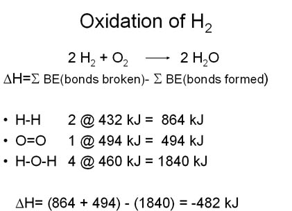
Energy Released from Combustion Reaction
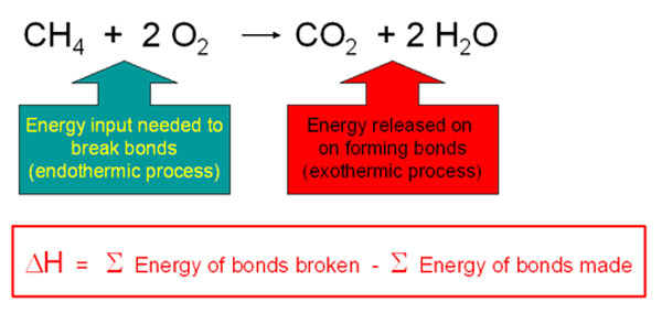
During chemical reactions, energy is either released to the environment (exothermic reaction) or absorbed from the environment (endothermic reaction). During chemical reactions, bonds are broken in the reactants and new ones are made in the products. Bond-breaking is an endothermic process and bond-making is an exothermic process. The average bond dissociation energies of some chemical bonds are shown in the following table.
Selected Bond Energies | |||
| Bond | Bond Energy(kJ/mole) | Bond | Bond Energy(kJ/mole) |
| H-H | 432 | C=O | 799 |
| O=O | 494 | C-C | 347 |
| O-H | 460 | C=C | 611 |
| C-H | 410 | C=C (aromatic) | 519 |
| C-O | 360 | N=O | 623 |
For any chemical reaction, the overall energy change, the enthalpy of reaction(DH), is the difference of all the energy absorbed in bond-breaking and all the energy released in bond-making.
DH = S BE(bonds broken)- SBE(bonds formed)
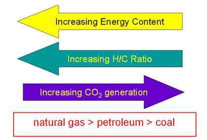
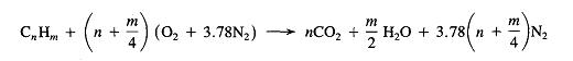
Combustion energetics can be estimated from the bond energies for all the classifications of fossil fuels. The amount of energy released is dependent on the oxidation state of the carbons in the hydrocarbon which is related to the hydrogen/carbon ratio. The more hydrogen per carbon, the lower the oxidation state and the more energy that will be released during the oxidation reaction. Thus the greater the H/C ratio, the more energy release on combustion.
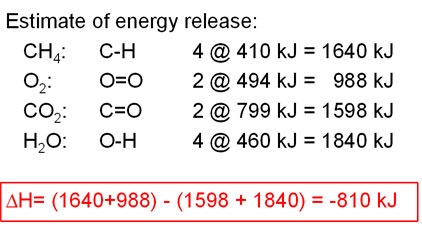
Every mole of methane (16 g) releases 810 KJ of energy on burning.
Petroleum has a large saturated hydrocarbons content. For estimating energy content, we can consider the molecule to consist of multiple -CH2-units. For calculating the expected energy release per CH2 unit, the energy of two C-H bonds and one C-C bond (since the carbon joins two neighboring groups and we are averaging) would be used which gives an energy content similar to that of methane ("natural gas"). However, petroleum also can contain a significant fraction of aromatic molecules depending on the nature of the petroleum distillate product. For example crude oil has an energy content of about 45.2 kJ/g while gasoline has a higher value of about 48.1 kJ/mole because it contains a smaller fraction of aromatics.
Coal is composed of primarily aromatic hydrocarbons, so we can consider the molecule to consist of multiple -CH- units. The actual average energy release per gram of coal from combustion is less than the predicted value since coal contains significant amounts of water and minerals. Hard coals such as bituminous or anthracite have larger energy content (29-33 kJ/g) than the soft sub-bituminous or lignite coals (17-21 kJ/g).
The average hydrogen/carbon ratios show that the degree of unsaturation increases from natural gas through petroleum to coal. The amount of carbon dioxide released per mole also increases as the amount of unsaturation increases. Since carbon dioxide is a greenhouse gas, from this data, it would appear that burning coal would have a larger greenhouse effect than burning natural gas.
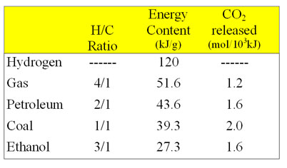
Ethanol (CH3CH2OH, a biomass derived fuel) is more highly oxidized than a hydrocarbon since it contains an oxygen and gives off significantly less energy on combustion than petroleum. Gasohol is a gasoline/ethanol mixture.
- Ethanol has a greater density
0.79 g/cc vs 0.70 g/cc
12% more ethanol per tank - Ethanol has a lower energy density
27.3 kJ vs. 43.6 kJ
produces ~40% less energy per gram
Gasification
Biomass gasification is an endothermic thermal conversion process whereby a solid fuel is converted into a combustible gas.

The product gas consists of carbon monoxide, carbon dioxide, hydrogen, methane, trace amounts of higher hydrocarbons (ethane), water, nitrogen (with air as oxidant) and various contaminants, such as small char particles, ash, tars, higher hydrocarbons and oils.
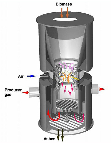
Source: Gasifier schematic by NRC
The Syngas produced by gasification is Incomplete Combustion and as such syngas can be much dirtier than the flue gas from complete combustion, I.e. depending on the process the hydrocarbon, tar, ammonia etc levels are very high.
Gasification allows for emissions reduction in that it is possible to clean the syngas to remove emission causing agents. The syngas combustion can then be done in a very clean and efficient manner.
Tars formed in the gasification process can readily condense on cool components downstream from the gasifier, resulting in plugging and fouling of pipes, tubes, and other equipment.
- Tars can severely engine operation (fouling, lubrication) and must be eliminated.
- Simple scrubbing approach has repeatedly failed to demonstrate long-term reliability and creates serious environmental problems because of large quantities of tarry water produced.
- Catalytic reforming followed by scrubbing is a preferred option.
- Tar formation can be reduced by separating the drying, devolatilization, gasification and combustion reaction steps (e.g. multi-stage gasifiers –

Source: GEK Experimeter's Kit


Monday, 16 April 2012
Rules of Thumb for Mechanical Seals
Before selecting your mechanical seal design there are three things you want to remember:
- All of the seal materials must be chemically compatible with any fluids that will be pumped through the system and that includes solvents, cleaners or steam that might be introduced into the system to flush or clean the lines. It also includes any barrier fluids that are used to circulate between dual mechanical seals.
- The seal faces must stay together. If they open, the seal will leak and allow solids to penetrate between the faces. The solids will eventually destroy the lapped surfaces.
- Good seal life is defined as running the mechanical seal until the carbon face is worn away. Any other condition is called a seal failure and is always correctable
Selecting materials - The elastomer ( the rubber part)
- There are two temperature limits for a mechanical seal:
- You must not exceed the temperature of the seal components. As an example, Ethylene Propylene rubber cannot seal hot fluids in excess of 300° degrees Fahrenheit ( 150° C) without taking a compression set and eventually leaking.
- You must not exceed the temperature limit of the fluid you're pumping. Many fluids will change from a liquid to a gas, solid or crystal at elevated temperature. In almost every case this will cause a seal failure. As an example: petroleum lubricating oil cokes between 250 and 300 degrees Fahrenheit (120° C. to 150° C.) and restricts the movement of the seal components. A Viton® O-ring, in this application would not have been subjected to its temperature limit, but you could have the seal failure because of the coking problem
- Halogens will attack Teflon® coated elastomers . Halogens are easily identified because they end in the letters " INE". The list would include Bromine, Chlorine. Astatine, Fluorine, and Iodine. These Halogens will penetrate the Teflon® coating and attack the base rubber material causing it to swell and split the Teflon sleeve or coating.
- Most Viton® compounds are attacked by water. Be sure to check if you have the recommended grade. Remember that steam is another name for water. The steam cleaning of lines is very common in the process industry. Caustic is another common cleaner tht contains a high percentage of water.
- Buna "N" (Nitrile) i has a short shelf life. This is the elastomer that is most often used in Rubber Bellows Seals. The problem is Ozone attack. Ozone is produced by the sparking of electric motors, so it is a very common problem. A typical shelf life for most Buna compounds would be one year.
- If a round O-Ring becomes square in operation (compression set) it's almost always caused by excessive heat. Chemical attack is usually recognized by a swollen and soft elastomer while high heat will produce a shrunken, hard one.
- Chemical attack of the elastomer will usually cause a seal failure within five to ten days. The swollen elastomer will "lock up" the mechanical seal and in some instances, open the lapped seal faces.
Determine the correct O-Ring by one of the following methods:
- Look up the chemical in published o-ring charts provided by all reputable seal companies.
- Check to see if your plant has any experience with o-rings , in this fluid,. O-ring can also be found in filters, strainers, valves, flanges, expansion joints etc..
- Test theo-ring by immersing it into the sealing fluid for one week. If the o-ring changes weight, shape, or appearance, it is not compatible with the fluid.
- Use a universal o-ring compound such as Green Tweed's Chemraz, Dupont's Kalrez® or a similar product.
- When choosing an o-ring , or any other elastomer, be sure to consider any cleaners or solvents that might be flushed through the lines, or that could come into contact with the seal. The elastomer must be compatible with these fluids also.
- Never use " glued together" elastomers in a split seal or any "dynamic" application. A hard spot will be created that will interfere with the movement of the dynamic elastomer.
Selecting Materials - The Faces.
- Carbon and most hard face materials have an expansion rate of about one third that of stainless steel.
- Use two hard faces if the product has a tendency to solidify between the seal faces. Never use plated or coated hard faces in these applications. Hard faces are recommended if you find that it is impossible to keep the seal faces together and solids are present in the sealing liquid. Two hard faces are also recommended in the sealing of hydrocarbons that have to pass a "fugitive emissions" test. Coke particles forming between the faces will pull pieces of carbon out of the carbon/graphite face presenting a leak path for fugitive emissions.
- Although many carbon graphite compounds are available, unfilled carbons are the best because they are corrosion resistant to almost all chemicals except oxidizing agents and some de ionized water applications. These oxidizing agents will combine with the carbon to form Carbon Monoxide and Carbon Dioxide. The most common oxidizers are oleum, sulfur trioxide, strong bleaches and nitric Acid. You cannot use any form of carbon in these applications. Keep in mind that black elastomers will also be attacked by oxidizing agents because of their carbon content.
- Ceramic vs. ceramic is a good choice for oxidizing chemicals.
- If you're going to use plated Tungsten Carbide as a face material, use only the nickel base Tungsten Carbide. Cobalt base is too hard and can crack with normal seal face differential temperatures. Nickel base, because of its superior corrosion resistance, is the preferred material for solid Tungsten Carbide faces also.
- Reaction bonded Silicone Carbide has excellent wear characteristics, but contains up to 17% free silica which can be attacked by many chemicals including caustic. Alpha sintered Silicone Carbide is also available and is Silica free.
- 85% ceramic should never be recommended as a hard seal face because it can break with as little as a 100 degree Fahrenheit (55 C) temperature difference. 99.5% would be a much better choice.
- Plating or coating a seal face will not give it corrosion resistance. Coatings are used for wear resistance and low friction. To get corrosion resistance the outer coating must be at least 1/8" (3 mm) thick. If the base material is not corrosion resistant to the pumping fluid and any cleaners or solvents used in the lines the corrosive will go through the coating and attack the base, causing the plating to come off in sheets.
Selecting Materials - The Metal Parts.
- Be sure to use low expansion metal such as Carpenter 42 or Invar 36 for your metal bellows seal face holder if the product temperature can exceed 400° Fahrenheit (205°C). These low expansion steels will prevent the carbon or hard seal faces from leaking between the face and the metal holder. Needless to say glue or epoxy is not a sensible solution to differential expansion problems.
- If your pump is manufactured from Iron, steel, stainless steel, or bronze, you can probably use a seal manufactured from 316 stainless steel components. The springs or bellows, however, must be manufactured from Hastelloy "C" to avoid problems with Chloride Stress Corrosion.
Sealing Limits
- Use only stationary mechanical seals (the springs do not rotate with the shaft) if the face surface speed exceeds 5000 feet per minute ( 25 M/sec.), but never in a cartridge design unless some method has been provided to insure that the cartridge sleeve is square to the shaft.
- Use o-ring balanced seals in vacuum applications down to 10-2 inches, or one millimeter of mercury (1 Torr.). The o-ring is the only elastomer that can seal both vacuum and pressure. Split seals will work in these applications, but they must be turned around for best operation.
- Any good quality, balanced, o-ring seal can seal stuffing box pressures to 400 psi (28 bar) and temperatures to 400 degrees Fahrenheit (205° C). There is a compound of Dupont's Kalrez® that is satisfactory to 600 degrees Fahrenheit (370° C), but it 's not acceptable at ambient temperatures (it gets too hard).
Application
- A Balanced o-ring seal should not vaporize the product at the seal face if the stuffing box pressure is at least one atmosphere above the products vapor point.
- The easiest product to seal is a cool, clean, lubricating liquid. All problem chemicals can be placed into several categories. If you know how to seal these categories you should have no trouble making seals work in your applications :
- Products that crystallize (caustic or sugar solutions)
- Viscous products (asphalt or molasses)
- Products that solidify (polymers or chocolate)
- Products that vaporize (hot water or benzene)
- Film building liquids (hot petroleum or plating solutions)
- High temperature fluids (heat transfer oil or liquid sulfur)
- Dangerous products (fire hazard, explosive, radioactive, bacteria)
- Non lubricating liquids (solvents or hot water)
- Gases and dry running applications (hydrogen)
- Dry solids (cake mix or pharmaceuticals)
- Corrosive fluids (acids or strong bases)
- Cryogenics (liquid nitrogen)
- Slurries (river water, sewage, most raw products)
- In addition to these chemical categories there are other sealing problems that include:
- High pressure
- Hard vacuum
- High speed
- Excessive motion
- Dual seals should be balanced in both directions to prevent failure when barrier fluid pressure changes. The practice of using "one direction" seal balance is commonly employed by most seal companies and should be avoided for both safety and reliability.
- Use motion seals on mixers, agitators, sleeve bearing equipment and any rotating device that has motion greater than 0.005" (0,15 mm.) in a radial or axial direction. Pump seals do not work well in these applications because the hard faces are too narrow and the internal seal clearances are too tight.
- Avoid using flushing fluid as a coolant in stationary mechanical seals. The coolant will be directed to only one side of the seal and since a stationary seal does not rotate the sliding components, the differential temperature can cause the faces to go out of flat. In the case of stationary bellows seals, it could cause a bellows rupture.
- The best way to cool a seal is to use the jacketed stuffing box that came as a part of the pump. This jacket will not only cool down the seal area, but will provide the necessary cooling to the shaft so that it will not transmit stuffing box heat back to the bearings.
- The use of steam in a Quench gland is another solution, but not as good as the jacketed stuffing box.
- It 's all right to dead end fluid in a stuffing box if a jacketed stuffing box is being used, but do not attempt to recirculate back to the suction side and cool the stuffing box at the same time. When using a jacketed stuffing box it is best to install a carbon bushing in the bottom to act as a thermal barrier between the pumping fluid and the seal.
- Do not use rotating, "Back to Back" double seals in dirt or slurry service. The solids will prevent the inner seal from moving forward as the faces wear and if the barrier fluid pressure is lost, solids can open and penetrate between the inner seal faces.
- Be sure to vent vertical pumps back to the suction side of the pump. Air trapped in the stuffing box can cause the seal faces to run hot and in some instances destroy the elastomer.
- Cyclone type separators, or "in line filters" are not a good method of cleaning up the fluid in the stuffing box.
- Heat affects a seal several ways:
- The faces can be attacked. Plated faces can have the hard coating crack off and filled carbons can have the binder melted out in high heat.
- The elastomer (rubber part) has a temperature limit determined by the compound used.
- The corrosion rate of all liquids increases with temperature.
- Thermal expansion can cause seal face loads to alter and seal face flatness to change.
- Many products will change from a liquid to a solid or gas at high temperature. If this should occur between the seal faces, they can be blown open.
- Do not be tempted to put the mechanical seal outside of the stuffing box to keep the springs out of the fluid. As the face wears, the seal must move into the slurry where it will eventually "hang up" and leak. In these applications centrifugal force is throwing solids into the lapped faces and if there is excessive pressure in the system the seal faces will be blown open.
- When choosing the pressure range of a mechanical seal be sure to consider the stuffing box pressure not the pump discharge pressure. Very few seals will ever see discharge pressure.
- Seals lapped to less than three helium light bands ( 0.000034") inches or 1,0 microns) should not show visible leakage. Visible leakage occurs at about 5 light bands.
- A typical mechanical seal face load would be 30 psi. (0,2 N/mm2) when the carbon is new and 10 psi. (0,07 N/mm2) when the carbon is fully worn away. You must never guess as to how much to compress a mechanical seal. Either take the information from the seal print or calculate the correct length from the above information.
- Both rotating and stationary metal bellows seals require vibration damping. Elastomer seals do not experience this vibration problem because the elastomer touching the shaft is a natural vibration damper. Vibration can be either harmonic or caused by poor lubricating fluids (slip stick)
- Use only non-fretting seal designs. Shafts and sleeves cost too much to ignore this severe problem.
- Carbon throat bushings should have a shaft clearance of 0.002 inches/inch (0,002 mm/ millimeter) of shaft diameter. If they are going to be used as a support bearing you should cut the clearance down to 0.001 inches/ inch (0,001 mm/millimeter) of shaft diameter.
- It is not necessary to lubricate seal faces at installation. If the product you are sealing can vaporize between the faces and cause freezing then you must remove any lubricant that might have been placed there by the manufacturer.
- Balanced mechanical seals consume about one sixth the horsepower of packing. Packing a pump would be like running your automobile with the emergency brake engaged. The car would run, but the fuel consumption would be high.
- Single spring seals are wound in either a right or left handed direction. Check to see if your seal will a problem in keeping the faces together because of the spring winding.
- Open impeller pumps require impeller adjustment. Use only cartridge or split seals in these applications. Do not use seals that locate against a shoulder or set screw to the shaft, as the face load will change when the impeller is adjusted.
- Do not relap the carbon face unless it's an emergency. Seal face opening is a common seal failure. When the faces open solid particles imbed them selves into the carbon face and will be driven in even further during the lapping process. If you must relap in an emergency never use lapping powder, as the abrasive particles will imbed into the soft carbon.
- You cannot balance an inside seal by removing material from the carbon face. To get seal balance you must do one of the following:
- Use a stepped sleeve with rotating seals.
- Let the carbon slide in a holder that is sealed to the shaft.
- Use a metal bellows. The balance is not perfect, but good enough.
- Use a stationary seal design, they require no stepped sleeves.
- Seal face hardness is a confusing subject because of the various measuring scales employed. The two most common are Rockwell "C" and Brinnell. If you divide the Brinnell scale by ten (10) it is almost equal to the Rockwell "C" scale.
- Avoid oil as a barrier or buffer fluid between two mechanical seals. Most petroleum base and other oils have a low specific heat (0.2 - 0.4) and combined with poor conductivity (0.5 of water) makes them a poor choice compared to fresh water. If oil is mandatory, a clean heat transfer oil would be your best choice.
- A convection tank can often be used between two balanced o-ring seals. If you use unbalanced seals the extra heat generated by this type of seal is usually excessive for convection cooling. Contact the seal manufacturer for his recommendations concerning speed, diameter, face combination and pressure limits for convection cooling. If convection is not satisfactory, a pumping ring or forced lubrication is another option.
- If you decide to repair your mechanical seals in house, be sure to purchase the parts from the original manufacturer. If you decide to have them repaired send them back to the original manufacturer. It 's important that the seal be rebuilt with the original materials and it must meet the original tolerances. This information is not available from the manufacturer because of product liability problems. It's more difficult to troubleshoot a repaired seal because old marks on the comonents can confuse the troubleshooter.
- O-ring seal designs can tolerate three to four times the "run out" capability of sliding or pusher seals incorporating wedges, chevrons, U- cups etc..
- Oil on the seal faces can cause the faces to stick together during long periods of non running. If you do not intend to run the equipment soon remove any oil that might be on the seal faces during the assembly procedure.
Reference:http://www.mcnallyinstitute.com
Saturday, 7 April 2012
Steam FACTS
At Atmospheric Pressure At 100 degree Celsius Water Contains 180 Btu per pound (418.8 kJ/kg)
At Atmospheric Pressure At 100 degree Celsius Steam Contains 1,150 Btu per pound (2,675 kJ/kg)
For water at atmospheric pressure, the heat of vaporization (latent heat that must be added above the saturation temperature of the water) is about 970 Btu per pound (2256.2 kJ/kg).
Volume Expansion is around 1600 times
Friday, 30 March 2012
Rating of Boiler
Boiler horsepower (BHP) is an obsolete non-metric measurement unit of power. Nevertheless, BHP is still used to measure boiler output in industrial boiler engineering in North America. One Boiler Horsepower (1BHP) is equal to a boiler thermal output of 33,475 BTU/h (British Thermal Units per Hour) or 9.81055407 kW (Kilowatts). This is the energy rate required to evaporate 34.5 lb (pounds) or 15.648936765 kg (kilograms) of fresh water at 212 °F (degrees Fahrenheit) or 100 °C (Celsius) in one hour (1h).
Large boiler capacity is generally given in lbs of steam evaporated per hour, under specified steam conditions. Maximum continuous rating is the hourly evaporation that can be maintained for 24 hours.
To convert horsepower (hp) into lbs of steam: Multiply hp x 34.5
Example: 100 hp x 34.5 = 3450 lbs of steam per hour
To convert lbs of steam to hp: Divide steam per hour by 34.5
Example: 8625 lbs of steam ÷ 34.5 = 250 hp boiler
Boiler Feed Water System
One of the most important factors in keeping your boiler on-line is to keep enough water in it. Otherwise the boiler will shutdown on a low water condition. This is especially true with firetube boilers that are fired automatically. That is why it is so important to size a feedwater system so that it has the capability of maintaining the proper water level in your boiler.
A) Sizing of Boiler Feed Water Tank
A properly sized feed water system will have a tank adequately sized to feed your boiler and pumps selected to deliver that water at the correct rate and pressure.
In most cases ten minutes of water should be readily available for your boiler. One boiler horsepower = 34.5 lbs/hr of steam (or water) from and at 212o F. We also know that one-gallon of water weighs 8.37 lbs. To calculate the storage tank needed use the following formula:
For example, if you have a 500 HP boiler the calculation will be as follows -
Now, it stands to reason that you can't operate your tank totally flooded so you have to allow for some extra room. A safety factor of 1.5 is generally the accepted rule of thumb.
We then take the 345 gallons and multiply by 1.5 to get 517.5 gallons and choose a tank size of 500 gallons (one of the standard tank sizes available).
B) Sizing of Boiler Feed Water Pump
For this example we will say that our relief valve is set at 150 psig and there is a 5 lb. pressure drop. The calculation will look like this:
A) Sizing of Boiler Feed Water Tank
A properly sized feed water system will have a tank adequately sized to feed your boiler and pumps selected to deliver that water at the correct rate and pressure.
In most cases ten minutes of water should be readily available for your boiler. One boiler horsepower = 34.5 lbs/hr of steam (or water) from and at 212o F. We also know that one-gallon of water weighs 8.37 lbs. To calculate the storage tank needed use the following formula:
BHP X 34.5 ÷ 8.337 lbs ÷ 60 min. X 10 = minimum usable capacity in gallons
For example, if you have a 500 HP boiler the calculation will be as follows -
500 x 34.5 ÷ 8.337 ÷ 60 X 10 = 345 gallons
Now, it stands to reason that you can't operate your tank totally flooded so you have to allow for some extra room. A safety factor of 1.5 is generally the accepted rule of thumb.
We then take the 345 gallons and multiply by 1.5 to get 517.5 gallons and choose a tank size of 500 gallons (one of the standard tank sizes available).
B) Sizing of Boiler Feed Water Pump
There are three areas that must be considered.
i) The correct flow rate in GPM
ii) The correct pressure needed
iii) NPSH (net Positive Suction Head)
i) Calculating the flow rate in GPM
For the example we have been using the calculation will look like this:
BHP X 34.5 ÷ 8.337 ÷ 60 X 1.5 = gpm
(Please note that the 1.5 is, once again, a safety factor.)
For the example we have been using the calculation will look like this:
500 BHP X 34.5 ÷ 8.337 ÷ 60 X 1.5 = 52 gpm
Another quick rule of thumb is that 1/10 of a gallon is needed for every boiler horsepower. So a 500 HP boiler will need a pump capable of delivering 50 gpm. An 800 HP boiler will need an 80 gpm pump.
ii) Calculating the Required Pressure
The next step is to determine the proper discharge of the pump. ASME code requires that you furnish feed water to your boiler at 3% higher than what the relief valve setting is on the boiler. In addition, you must take into consideration any pressure drops between the pump and the boiler. This would include any valves and piping.
For this example we will say that our relief valve is set at 150 psig and there is a 5 lb. pressure drop. The calculation will look like this:
150 x 1.03 + 5 lb drop = 160 psig required.
iii) Calculating Net Positive Suction Head
The last piece of the puzzle is the correct NPSH, net positive suction head. This is the amount of liquid, in feet, required at the pump suction to prevent cavitation and insure the pump is working correctly. This will help determine the tank stand height you will need.
This is the minimum absolute pressure at the suction nozzle at which the pump can operate. To avoid pump cavitation, the NPSHA of the system must be greater than the NPSHR of the pump. In other words, the available NPSH must be higher than the required. We have always sized our deaerator stands to be two feet higher than the NPSH needed for the pump selection. Remember, the water level in the storage tank adds to the safety margin.
To chose the correct NPSH refer to the pump selection tables. These tables are based on the pumps having the lowest possible NPSH needed. This is done to ensure the lowest tank stand and thus reduce the overall height of the boiler feed system. NPSHA is the feet available under the tank and NPSHR is the feet required by the pump. Check the pump curve for the NPSHR and then add one foot.
Pump capacity depends upon evaporation rate of the boiler. A safe figure for an on-off application would be 2 times the evaporation rate of the boiler. With a modulating level control, a factor of 1.3 times the evaporation rate plus recirculation is recommended.
Courtesy: http://www.mckenziecorp.com
Saturday, 7 January 2012
Material Selection Considerations for Various Forms of Corrosion
In order to prevent corrosion related failure modes from occurring they should be considered during the design and material selection stages of system development. Accounting for many of the issues that are correlated with corrosion, including test, design, and metallurgical factors facilitates the development of an inherently corrosion resistant design. This article addresses the major considerations for the common forms of corrosion that factor into design and material selection, and presents some general ‘rules of thumb’ used in selecting materials for corrosion resistance.
The ‘rules of thumb’ are contained in the following sections that address each of the main forms of corrosion. The sections identify the major failure modes, followed by discussions of the test, design, and metallurgical considerations. With respect to test and design considerations, the primary properties used for quantitative measurement, if there are any, are identified. For many forms of corrosion, there are no quantitative measurement techniques, and thus materials are only rated based upon their relative susceptibilities. Additional design features that are conducive to the creation of corrosive microenvironments are highlighted. The primary metallurgical factors for each form of corrosion are also identified. Some of the major material classes are discussed as to their relative susceptibility and resistance to the form of corrosion under consideration. Together, this information provides a basis for the down-selection of candidate materials. The information discussed above has been organized into six categories for each form of correction including :
- measurement
- design considerations
- misapplication of data
- metallurgical features
- susceptible alloys
- resistant alloys.
Subscribe to:
Posts (Atom)